Creating a Blueprint Node with C++
This post is about creating a new Blueprint node in c++ to rotate an Actor object around a pivot point.
The image below shows a mesh (called SM_Arm) that was imported into Unreal from a FBX file generated in Blender.
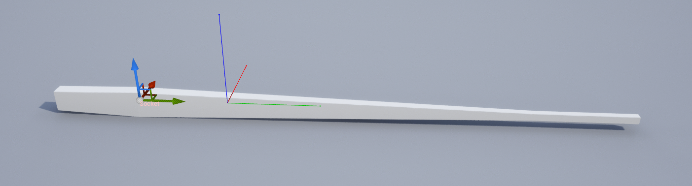
The gizmo on the left is at the position of a socket. The red, green and blue lines near the middle indicate the origin of the mesh, which is where the origin was in the Blender model.
We create a new blueprint actor, add a Static Mesh component, and set the mesh to SM_Arm. If we place this actor in the world, select it in the outliner, and press E to rotate it, the rotation gizmo (which indicates the pivot point around which it will rotate) is positioned on the origin of the SM_Arm mesh:
Manual Rotation
If we want to manually rotate around the socket position, we can use ALT-middle-mouse-click to temporarily move the pivot point like so:
Once we have applied a rotation the pivot point will return to the original position.
Blueprint Rotation
Header File
No existing single blueprint node supports rotating an actor around a specified pivot point, so as an exercise I decided to write one.
A blueprint node can be implemented as a static function on a c++ class which is derived from
the UBlueprintFunctionLibrary class. To create such a node use the Tools | New C++ Class menu option and create a class
derived from UBlueprintFunctionLibrary. In this example the new class is called "UtilityFunctionLibrary".
Unreal will create the header and implementation files. The header looks like this:
#pragma once
#include "CoreMinimal.h"
#include "Kismet/BlueprintFunctionLibrary.h"
#include "UtilityFunctionLibrary.generated.h"

UCLASS()
class MYPROJECT8_API UUtilityFunctionLibrary : public UBlueprintFunctionLibrary
{
	GENERATED_BODY()
};
There are no methods on the new class. We can add one like so:
#pragma once
#include "CoreMinimal.h"
#include "Kismet/BlueprintFunctionLibrary.h"
#include "UtilityFunctionLibrary.generated.h"

UCLASS()
class MYPROJECT8_API UUtilityFunctionLibrary : public UBlueprintFunctionLibrary
{
	GENERATED_BODY()

	UFUNCTION(BlueprintCallable, Category = "Utility")
	static void RotateActorAroundPivot(
		AActor* Actor,
		const FVector& PivotLocation,
		const FRotator& DeltaRotation );
};
The new function RotateActorAroundPivot takes as parameters the actor object we want to rotate, the pivot point we want to rotate it around, and the size of the rotation.
UFUNCTION Declaration
There are a couple of improvements we can make to the declaration of the RotateActorAroundPivot function, which currently looks like this:
- we can make the Actor parameter default to "self", which is the actor which this blueprint is a part of, by adding
meta = (DefaultToSelf = "Actor")to the UFUNCTION declaration - we can make the node easier to use by making the parameters optional (so they will be replaced by default values), by making them values, not references.
The updated declaration looks this this:
UFUNCTION(BlueprintCallable, Category = "Utility", meta = (DefaultToSelf = "Actor"))
static void RotateActorAroundPivot(
	AActor* Actor,
	const FVector PivotLocation,
	const FRotator DeltaRotation);
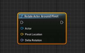
and the node now looks like this:
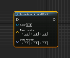
Implementation
The implementation of the node contains the maths operations needed to rotate the actor around the pivot point:
void UUtilityFunctionLibrary::RotateActorAroundPivot(
	AActor* Actor,
	const FVector PivotLocation,
	const FRotator DeltaRotation)
{
	if (!Actor) return;
	Actor->AddActorWorldRotation(DeltaRotation);
	FVector NewActorLocation = Actor->GetActorLocation();
	NewActorLocation -= PivotLocation;
	NewActorLocation =
	   FRotationMatrix(DeltaRotation).TransformPosition(NewActorLocation);
	NewActorLocation += PivotLocation;
	NewActorLocation -= Actor->GetActorLocation();
	Actor->AddActorWorldOffset(NewActorLocation);
}
This code is very substantially based on the code the editor uses to implement manual rotation.
Usage
This blueprint shows an example usage:
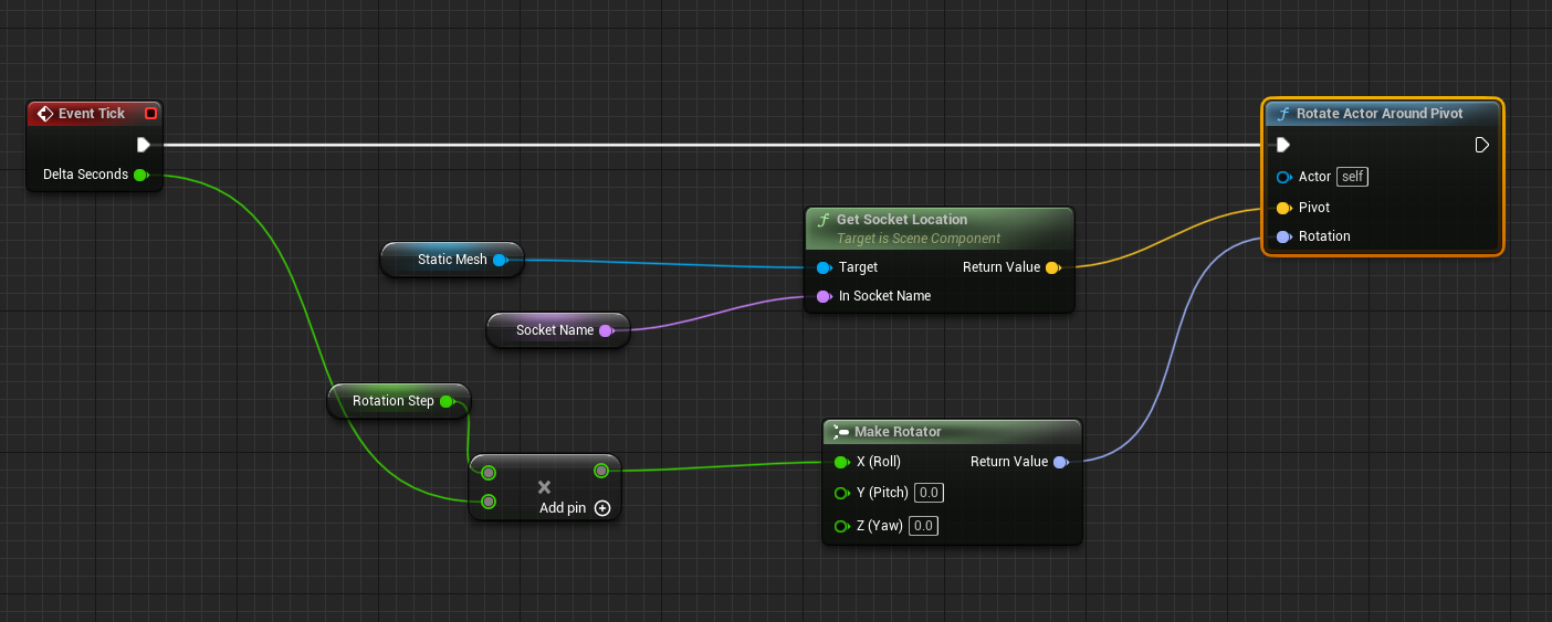
Every tick it:
- multiplies the tick duration by a factor (the Rotation Step variable) to calculate a rotation amount
- finds the location of the named socket on the Static Mesh component of the actor
- and rotates the actor around the position of that socket.
(This does not need sockets to work, the pivot location could come from anywhere.)
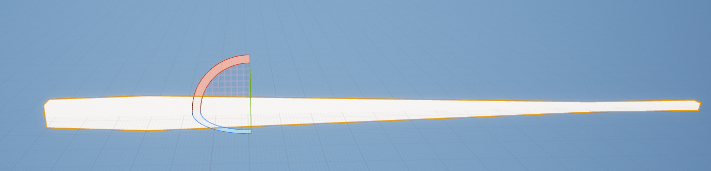
If the socket name is left blank, so the socket location is (0,0,0), the mesh rotates around its origin like so:
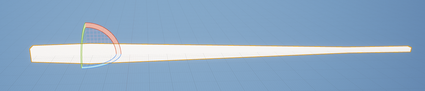
Whereas if a socket is chosen which is on the narrow end of the arm mesh, the rotation is like this:

Feedback
Please leave any feedback about this article here