Experiments With Chaos Physics - Using Blueprints
This describes some initial steps in using chaos physics in Unreal Engine 5.0.2.
The image below shows a working recreation of a medieval trebuchet built at Warwick Castle in England.
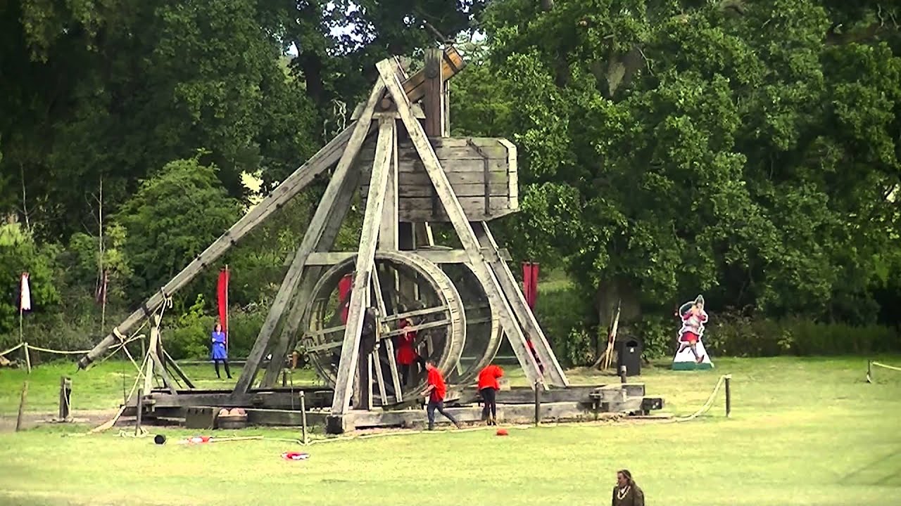
Image is from https://www.youtube.com/channel/UC89LF5ncbTZi9MukrMSN8eQ (c) Copyright the author.
This article describes the steps I took to create a working trebuchet model in Unreal Engine.
Blender Model
The image below show an unshaded blender model of the trebuchet.
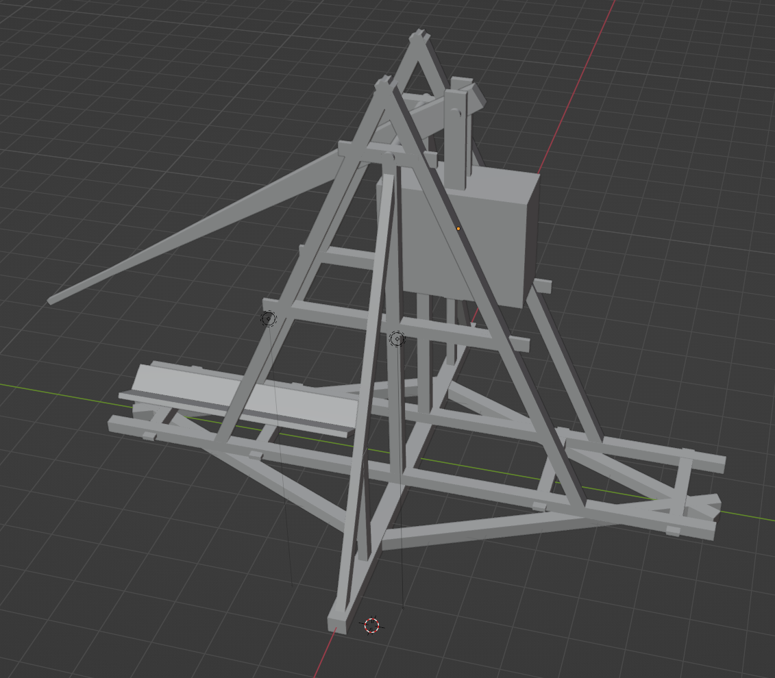
This model is constructed of these parts:
- the base
- the arm
- the counterweight
- the ramp
Each of these was exported from Blender in FBX format using these options
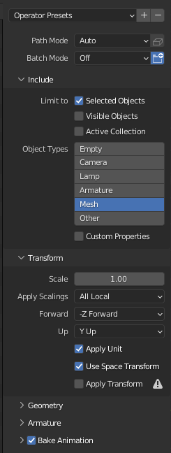
Exporting at the Origin
Before exporting it, each component was moved to the origin in Blender. This makes it easier to work with the meshes once they are imported into Unreal. It makes the local coordinate system meaningful.
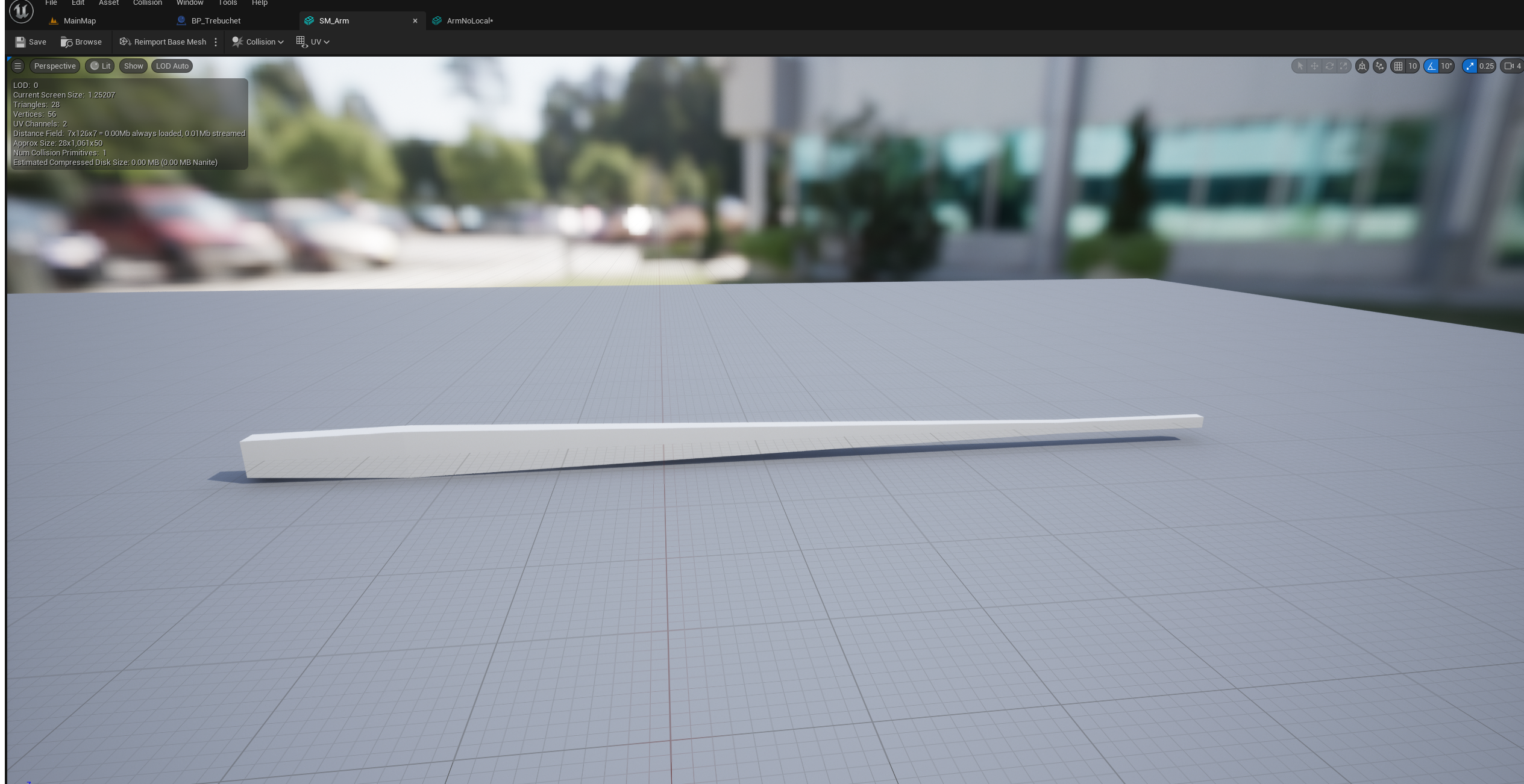
Taking the arm component as an example, if it is centered on the world origin in Blender and then exported, in Unreal it looks like this:
If it is not centered on the world origin in Blender, in Unreal it looks like this:
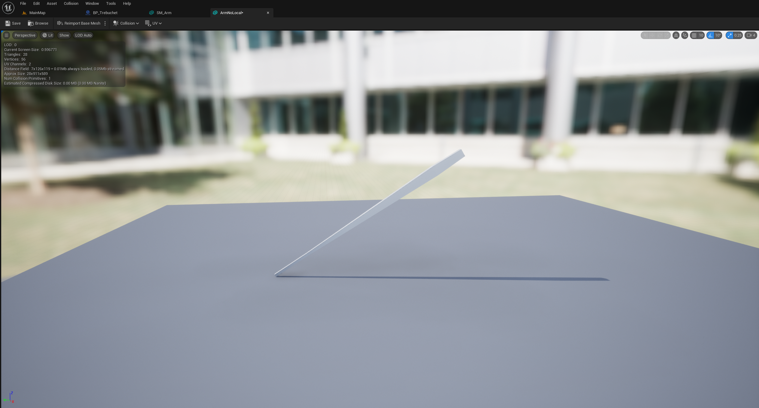
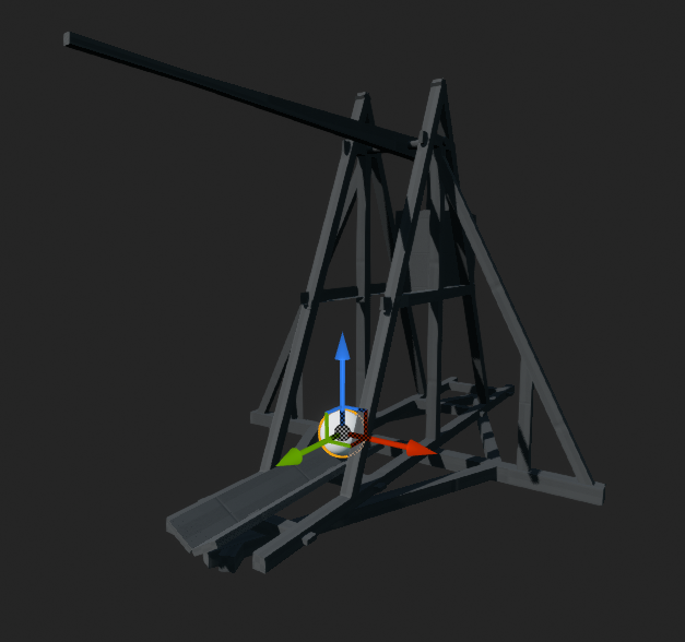
The difference in the position of the arm's origin effects how it easy it is to manipulate once the FBX file has been imported as a mesh and referenced by a Static Mesh component in blueprint. As this image shows, when the arm is positioned at the world origin in Blender, the Unreal transform gizmo (using world coordinates) is centered on the arm origin:
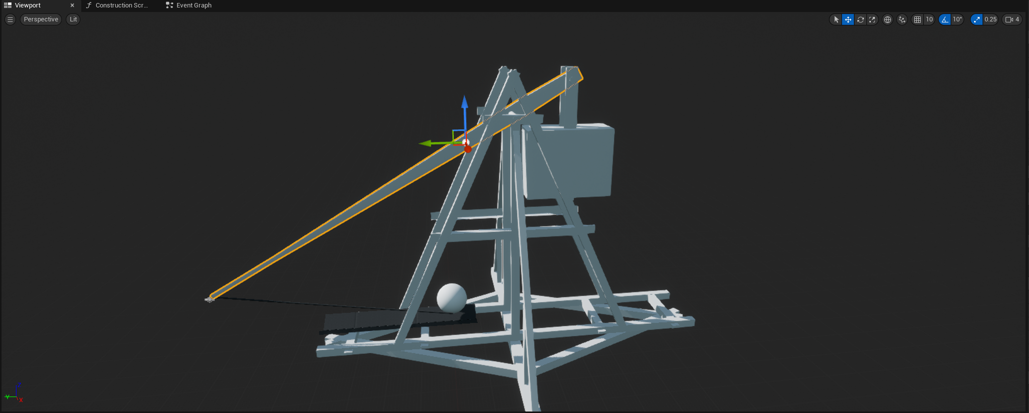
and when using local coordinates the Unreal transform gizmo is centered on the arm origin and aligned parallel with the arm to make it easy to position and rotate the arm.
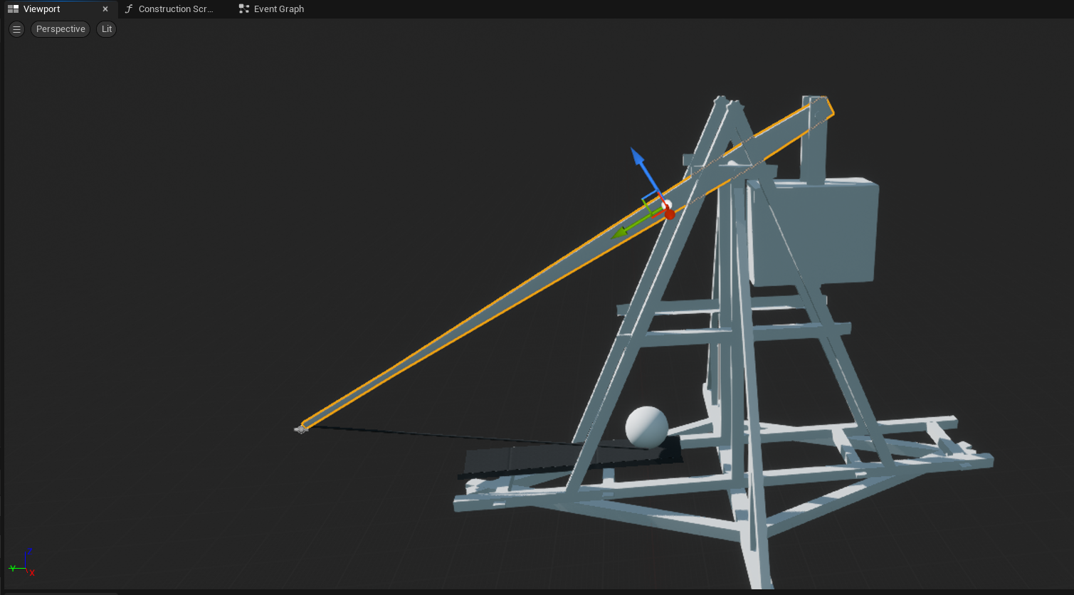
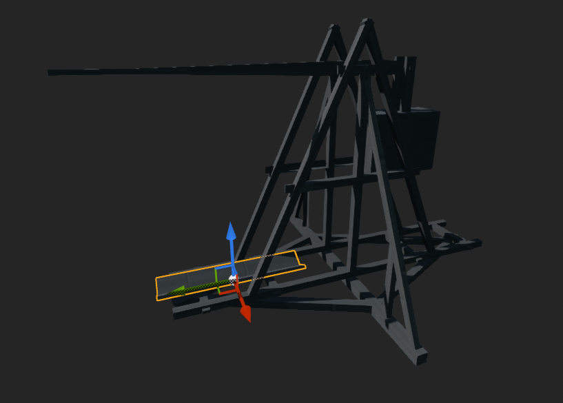
If the arm is not centered on the world origin in Blender before it is exported, this is what it looks like in Unreal:
The Unreal transform gizmo is not positioned on the arm, making it harder to position, and the local and world coordinate systems are the same, making it difficult to rotate without manually changing the pivot point.
Using Chaos Physics
To get to the position where we can start adding Physics Constraints, perform these steps to import the FBX files exported from Blender and create a blueprint trebuchet object:
- launch Unreal Editor
- create a new project with the Games, Blank, Blueprint options
- make new folders under the "Content" folder called "Blueprints" and "Meshes"
- open the Meshes folder and drop in Arm.fbx, Weight.fbx, Ramp.fbx and Base.fbx
- rename these meshes SM_Arm, SM_Weight, SM_Ramp, and SM_Base respectively
- in the Blueprints directory create a new blueprint derived from the Actor parent class. Rename this BP_Trebuchet
- open BP_Trebuchet in the blueprint editor
- add a Static Mesh component
- rename this "Base"
- set its static mesh property to "SM_Base"
- set its mobility property to "Static"; this will change Collision Presets to BlockAll
- drag the Base component and drop it on the "DefaultSceneRoot" to make it the root component
- add another Static Mesh component
- rename this "Arm"
- set its static mesh property to "SM_Arm"
- set Simulate Physics to checked, this will change Collision Presets to PhysicsActor
- set its mass to 505 kg which is calculated from its volume and the density of ash
- set Enable Gravity to checked
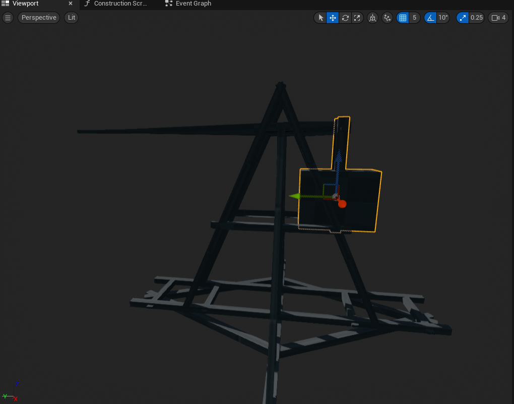
- position the arm to intersect the base axle like so:
Things fly apart
If you press the Simulate button now you will see something like this:
What's happening here is that the base and the arm are colliding; in their start positions they are occupying the same space where the arm intersects the base axle. The chaos physics solver tries to push them apart violently.
This can be prevented by adding a Physics Constraint component to BP_Trebuchet.
Preventing Collisions using Constraints
A Physics Constraint can apply linear and angular forces to objects, and constrain the interactions between objects. It can also disable collisions between objects, which is what we want to do, so we:
- add a Physics Constraint component
- rename it "ArmBaseStopCollision"
- set Component Name 1 to "Base"
- set Component Name 2 to "Arm"
- under "Constraint Behaviour" set Disable Collision to checked
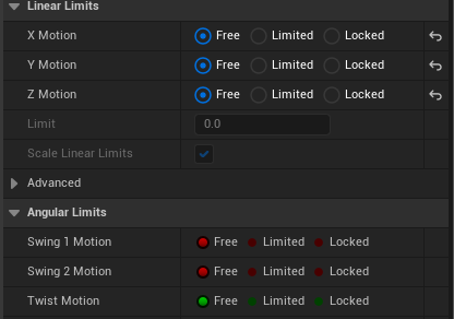
- set all the linear and angular limits to Free so this constraint does not affect the motion of the arm, like this:
Now if you press the Simulate button now you will see something like this:
This is what we expect, the arm falls because gravity acts on it, and we have disabled collision with the base so the arm falls right through the base. (If you are using Unreal 5.0.2 you might need to close the blueprint editor window and reopen it to reset the simulation)
Preventing Collisions using Channels
Another way of preventing the arm and the base from colliding is to use a custom Object Channel. We can create a custom Object Channel which represents a type of object. We assign this type to the base component, and then configure the arm component not to collide with objects of this type.
From the menu choose Edit | Project Settings... and
on the left hand side choose Collision, you will see this screen:
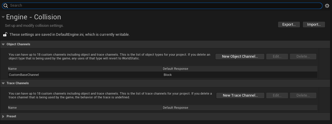
Click the "New Object Channel" button to create a new channel. On the screen above you can see we have already added a custom channel cells "CustomBaseChannel"
Edit the BP_Trebuchet blueprint and select the Base StaticMesh component.
Set the collision properties like this:
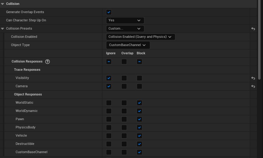
This tells Unreal that when resolving collisions the base should be considered to be of type "CustomBaseChannel".
Next select the Arm component and configure the collision properties like this:
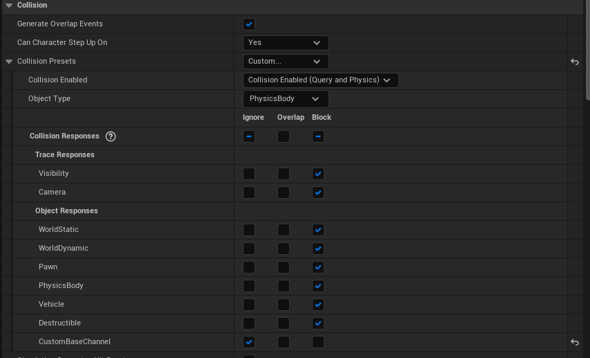
This tells Unreal that when the arm collides with something of the "CustomBaseChannel" type, to ignore that collision.
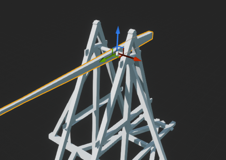
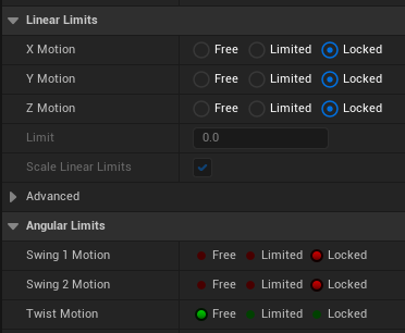
Constraining the Arm
We want the arm to pivot around the axle. If we change all the Linear Limits to Locked, and change Swing 1 Motion and Swing 2 Motion to locked, leaving Twist Motion as Free, the only way the arm can move is to pivot is around the X axis.
Looking at the tooltip for Twist Limit it sort of explains what Twist Motion does: "Symmetric angle of roll along the X-axis". This tells us the Twist Motion properties control the twist around the X-axis of the constraint, not the X-Axis of the constrained components. You can see this by changing the yaw angle (rotation around the local X-axis) of the constraint - at 45 degrees the arm just tips over slightly, at 90 degrees nothing happens at all.
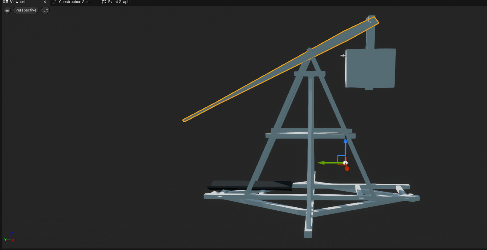
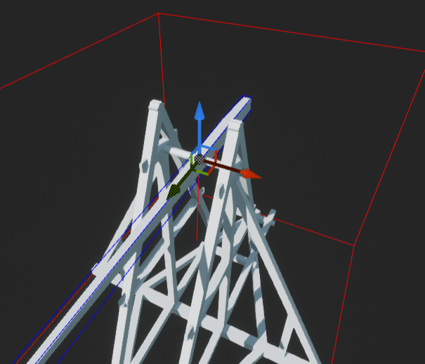
Looking at the image below, we can see the constraint X-axis (the red one) is pointing parallel to the axle which is what we want.
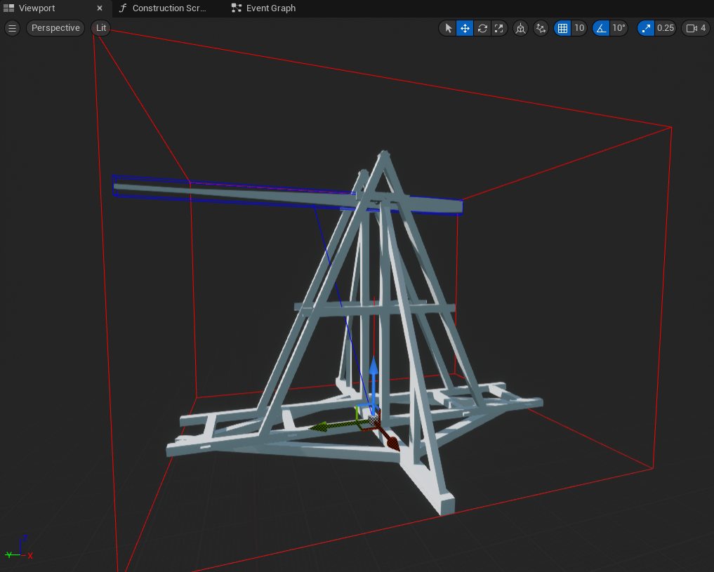
If we press the Simulate button from this position the arm pivots around the position of the constraint like so:
If we position the constraint where the axle is like this:
Then we get the arm swinging in the way we want:
Adding the Counterweight
Add another Static Mesh component:
- rename this "Weight"
- set its static mesh property to "SM_Weight"
- set Simulate Physics to checked, this will change Collision Presets to PhysicsActor
- set its mass to 4506 kg which is calculated from its volume and the density of stone
- set Enable Gravity to checked
- position the weight to intersect the arm like so:
Add a Physics Constraint component to link the weight to the arm:
- rename it "ArmWeightConstraint"
- set Component Name 1 to "Arm"
- set Component Name 2 to "Weight"
- under "Constraint Behaviour" set Disable Collision to checked
- move the constraint to where the weight is attached to the arm
Add another Physics Constraint just to stop the weight colliding with the base:
- rename it "BaseWeightConstraint"
- set Component Name 1 to "Base"
- set Component Name 2 to "Weight"
- under "Constraint Behaviour" set Disable Collision to checked
- set all the limits to Free so it does nothing but disable the collision:
Preventing Collisions using Collision Meshes
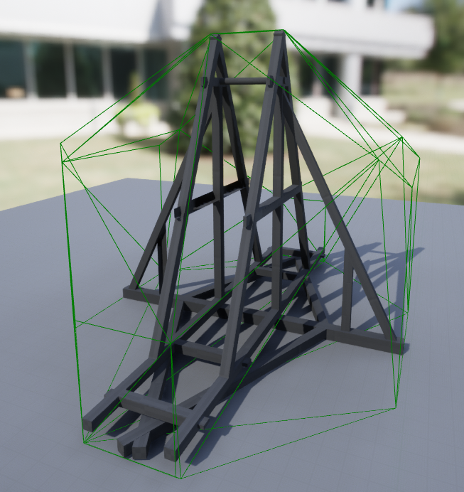
Even though we can see that the base and the weight do not collide the BaseWeightConstraint constraint is necessary because the base is using a simple collision volume. Open the SM_Base mesh and click Show | Simple Collision, this shows that the base is using a collision volume which includes the area where the weight swings:
An alternative to adding the BaseWeightConstraint constraint is to use the complex collision volume for the base. Click Show | Complex Collision to show the more complex and better fitting collision volume:
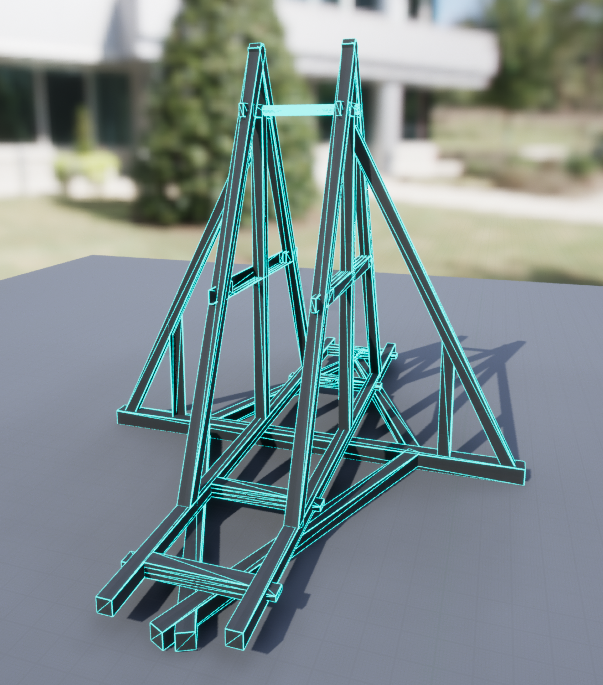
We can use this by changing the Collision Complexity property of the SM_Mesh to "Use Complex Collision as Simple" which will make Unreal use the complex collision volume in all cases.
Now when simulating the weight should pull the arm down like so:
Adding the Ramp
The ramp is a separate mesh which the projectile slides along when it is launched. It is added by:
- adding a new Static Mesh to BP_Trebuchet component
- rename this "Ramp"
- set its static mesh property to "SM_Ramp"
- set its mobility property to "Static"; this will change Collision Presets to BlockAll
- position it like this:
Adding the Projectile
The projectile is Sphere component. In theory it could be a separate actor because there can be many projectiles, and when they are thrown the move far away from the trebuchet, but for the purposes of learning chaos physics a component will suffice.
Add the projectile by:
- adding a new Sphere component to BP_Trebuchet component
- rename this "Ball"
- set Simulate Physics to checked, this will change Collision Presets to PhysicsActor
- set its mass to 15 kg
- set Enable Gravity to checked
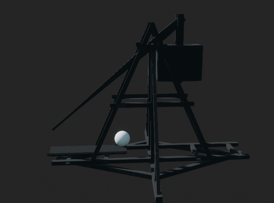
- position it on the ramp like this:
When the real trebuchet fires the arm is positioned close to the ground as shown in the top picture, so rotate the arm to a similar position like this:
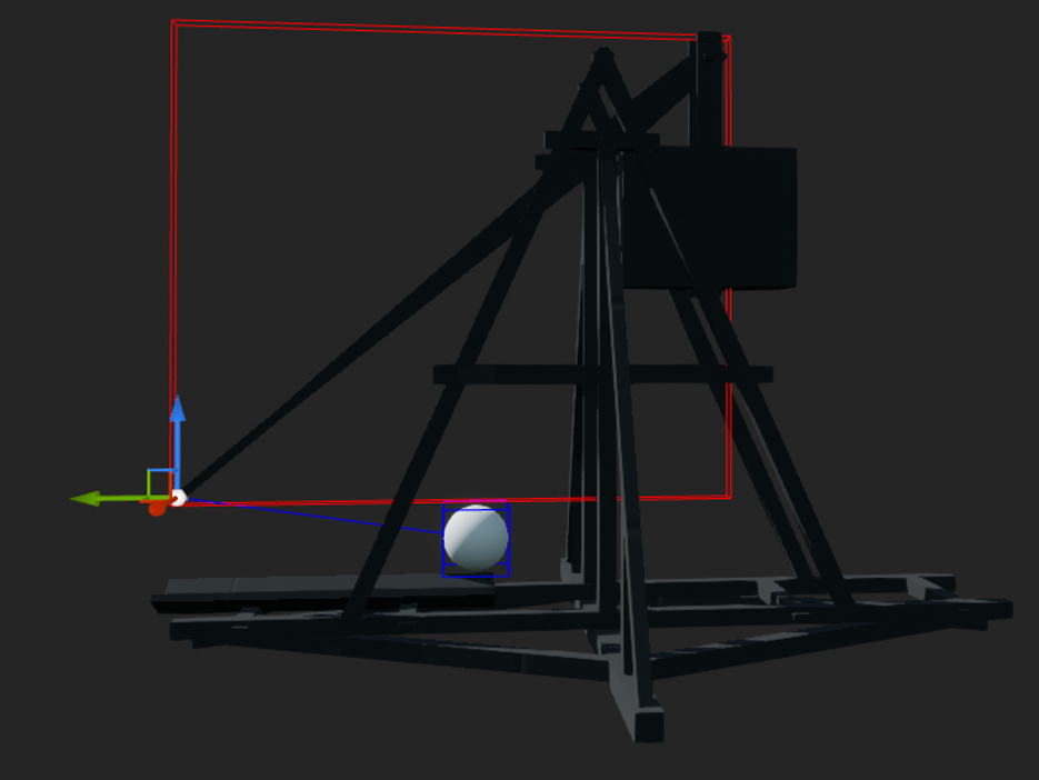
We will use a Physics Constraint to represent the connection between the arm and the ball:
- add a Physics Constraint component
- rename it "CableConstraint"
- set Component Name 1 to "Arm"
- set Component Name 2 to "Ball"
- under "Constraint Behaviour" set Disable Collision to checked
- set all the linear limits to Locked and all the angular limits to Free
- position the constraint at the end of the arm like this:
Now pressing Play in the editor should result in this motion:
Releasing the Projectile
The ball swings in the manner we want, but it remains connected to the arm. We need to find a way to break the constraint connecting the ball to the arm. There are several ways to do this, we could for example:
- break the constraint when the ball enters a certain area
- break the constraint when the ball is travelling at a certain angle
- break the constraint when the ball is travelling at a certain velocity
We can visualize the velocity using a blueprint like this:
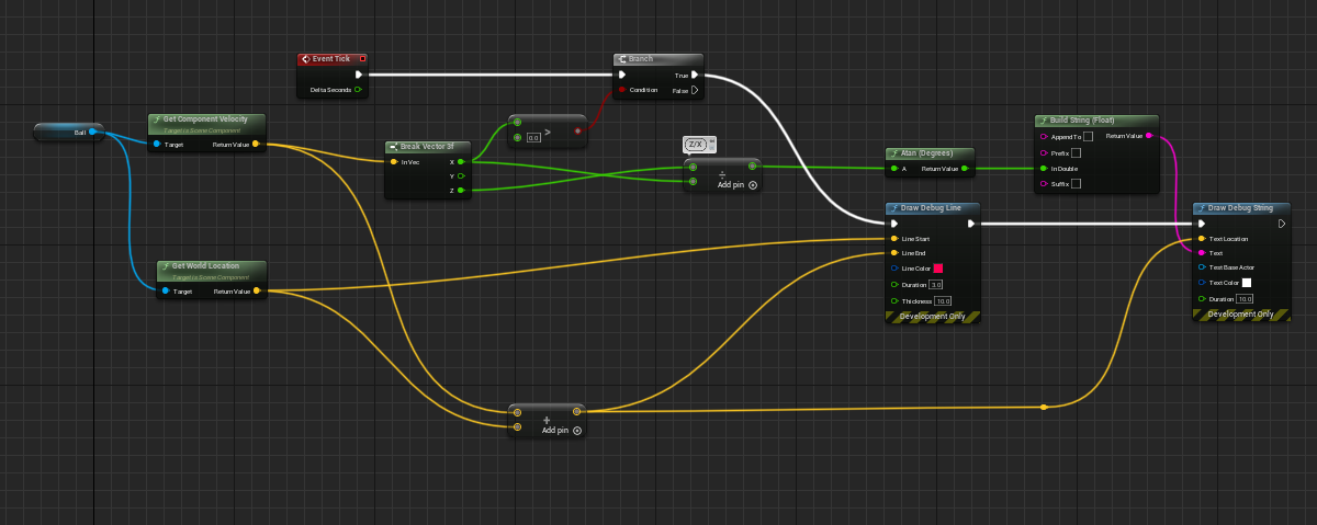
Assuming the trebuchet is aligned to fire down the X-axis, when the velocity in the X direction is greater than zero this blueprint will:
- draw a vector representing the velocity of the ball, so a longer line represents a greater velocity
- print the angle of the velocity at the end of each vector
The output looks like this:
This is the last frame:
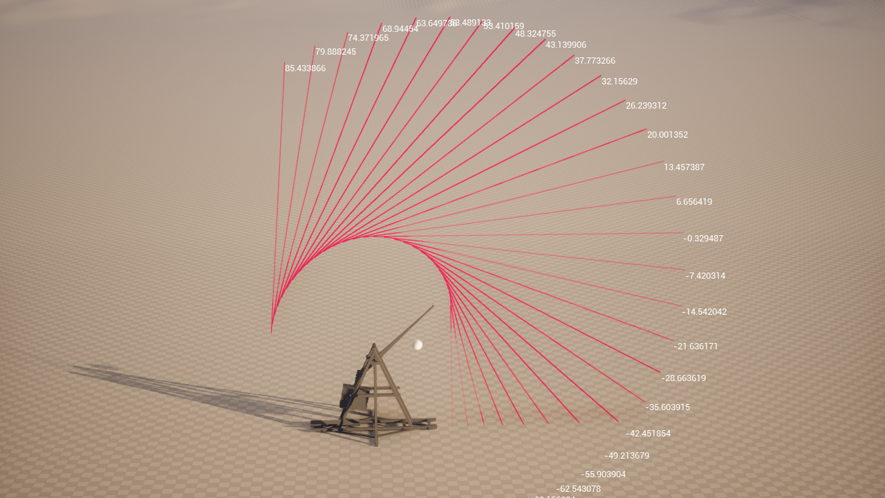
If we arbitrarily decide to fire when the angle is about 45 degrees, we can calculate the angle of the projectile from the velocity, and break the constraint between the arm and the ball as soon as the angle is less than 45 degrees.
We update the blueprint by adding a variable to track if the constraint has been broken, and break the constraint the first time the angle is less than 45 degrees:
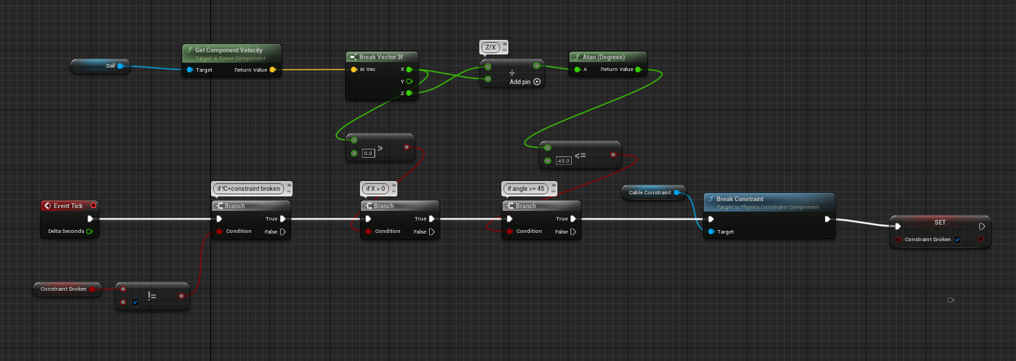
And we get this result:
References
Feedback
Please leave any feedback about this article here